
VR Module · Mechanical & Aerospace · Engineering
Turbofan Jet Engine
Applied Thermodynamics - Propulsion - Brayton Cycle
See it
Inside the module.
Learning objectives
By the end of this module, students will be able to:
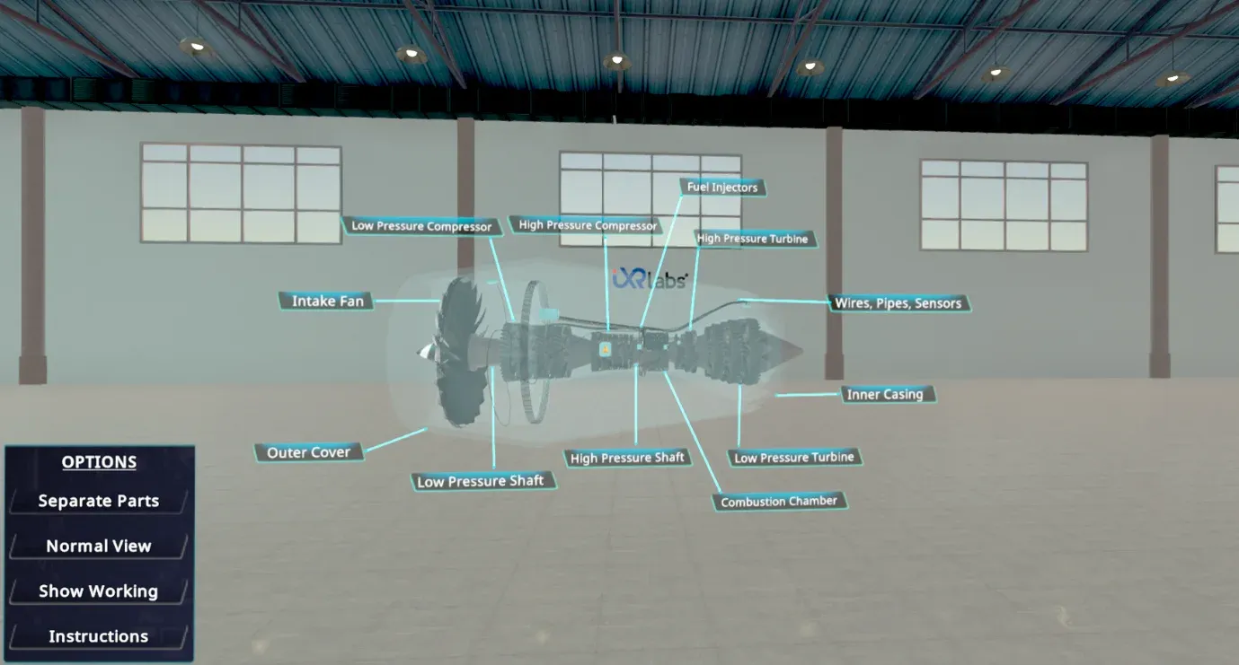
Identify the major components - fan, compressor, combustor, turbine, shaft, nozzle, and bypass duct
Explain the function of each component and how energy transfers across the engine stages
Describe the complete working from air intake to thrust generation
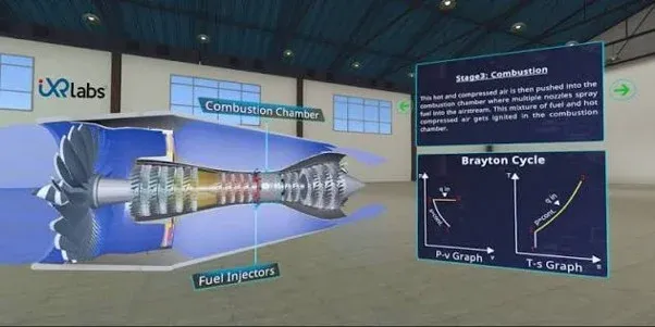
Correlate engine operation with the Brayton cycle - compression, combustion, expansion, exhaust
Interpret airflow, pressure, temperature, and velocity changes from CFD-style diagrams
Experiment on the test bench and observe changes in thrust, efficiency, and pressure ratio
A turbofan you can take apart and run.
A turbofan is an air-breathing engine that compresses incoming air, burns a portion of it with fuel, and drives the turbine with the hot exhaust to produce thrust. Most of that thrust comes from the large front fan and its bypass airflow - what makes turbofans efficient for high-speed aircraft.
Students don't just look at a static 3D object. In Assembly / Disassembly Mode they separate and inspect every component; in X-Ray View internal airflow paths and rotating assemblies become visible without dismantling; in Working Mode the full cycle is animated - intake, compression, combustion, turbine rotation, exhaust, and thrust.
A CFD visualisation layer shows airflow, pressure zones, and temperature variation across fan, compressor, combustor, turbine, and nozzle, all mapped directly to the Brayton cycle. In Simulation / Test Bench Mode learners vary operating parameters and watch performance respond - turning the model into virtual experimentation, lab demonstration, and pre-/post-lab assessment.
Why a virtual turbofan?
- No engineering department can dissect a real turbofan. The cost and the tooling put it out of reach.
- Airflow, pressure and temperature across the stages are the whole story, and all three are invisible.
- Bypass flow is what makes a turbofan efficient, and it is the hardest part to picture from a section drawing.
- A test-bench mode lets students vary parameters and see performance respond, which turns a model into an experiment.
Components you can inspect
- Intake fan and bypass duct
- Low- and high-pressure compressors
- Combustion chamber and fuel injectors
- High- and low-pressure turbines
- Shafts and bearings
- Exhaust nozzle
- Outer casing, wires, pipes, and sensors
Concepts it makes tangible
- The complete path from air intake to thrust
- The Brayton cycle - compression, combustion, expansion, exhaust
- How energy transfers across the engine stages
- Airflow, pressure, temperature, and velocity changes
- The role of bypass air in a turbofan
- Thrust, efficiency, and pressure ratio
Modes of interaction
- Assembly / Disassembly with every component labelled
- X-Ray / CFD-style airflow visualisation
- Working Mode maps combustion to the Brayton cycle
- Test-bench experiments vary parameters and show the response
How faculty use it
- Pre-lecture primer on propulsion and thermodynamics
- Flipped classroom - explore the engine before class
- Lab-free access to an engine no department can dissect
- Assessment of components, cycle, and performance
The 7thi AI tutor sits alongside the whole experience, scaffolding the difficult parts and giving subject-aware answers in context. Built-in assessment lets faculty see, per student, who has grasped which concepts - without grading another paper.
How the module works
Students take a turbofan apart and run it. Disassembly separates the intake fan and bypass duct, the low- and high-pressure compressors, the combustion chamber and fuel injectors, the high- and low-pressure turbines, the shafts and bearings, the exhaust nozzle and the outer casing with its wiring and sensors. A CFD-style visualisation then shows airflow paths, pressure zones and temperature across every stage, including how bypass air splits from the core flow and where most of the thrust actually comes from. The working mode maps intake, compression, combustion, turbine expansion and exhaust onto the P-v and T-s diagrams, and a test-bench mode lets students vary parameters and watch performance respond.
What students take away
A student can name every major component of a turbofan and explain its function, map the engine onto the Brayton cycle, and explain how bypass flow makes a turbofan efficient. In test-bench mode they can vary operating parameters and interpret the effect on performance, turning a static model into genuine virtual experimentation suitable for pre-lab and post-lab assessment.
In the classroom
Propulsion and applied-thermodynamics courses use the module to give students access to an engine no department can dissect. It serves as a flipped-classroom primer on the Brayton cycle, as a lab-free source of hands-on experience for aeronautical and aircraft maintenance programmes, and, through its test-bench mode, as a platform for genuine virtual experimentation that can be set as pre-lab or post-lab assessment.
Interactive features and modes
The module supports full assembly and disassembly, CFD-style visualisation of airflow, pressure and temperature across the stages, an animated working cycle mapped to the P-v and T-s diagrams, and a test-bench mode where operating parameters can be varied and performance watched in response. That last mode is what turns a 3D model into genuine virtual experimentation, suitable for pre-lab and post-lab assessment rather than passive viewing.
Why it matters
The turbofan is the engine that made mass air travel possible, and it is the richest single application of the Brayton cycle a propulsion student will meet. No engineering department can dissect a real one: the cost and tooling put it far out of reach, and even if a cutaway is available, airflow, pressure and temperature across the stages remain invisible. Bypass flow, the very thing that makes the engine efficient, is the hardest feature to picture from a drawing. A virtual engine gives every student a machine they can take apart, run and push.
The bigger picture
A turbofan compresses the entire Brayton cycle into a single machine, and its efficiency rests on the one feature hardest to picture from a drawing: the bypass flow that moves a large mass of air relatively slowly around the core. Understanding where thrust actually comes from, and how airflow, pressure and temperature change stage by stage, is central to propulsion engineering and almost impossible to grasp from a static section. Being able to take the engine apart, visualise the internal flow and then vary parameters on a test bench turns an abstract cycle into an engine students can genuinely investigate.
Devices, deployment and assessment
Deploying the module is straightforward. It runs on Meta Quest, ClassVR and Pico headsets, on WebXR-compatible browsers, and on the desktop without any headset at all, so a department can start with the hardware it already has and scale as it grows. Faculty can assign the whole module or specific scenes, set it as pre-lab preparation or post-lab revision, and track progress on a dashboard that records concepts mastered, time per scene and assessment scores, with export to the LMS via xAPI. The 7thi AI tutor answers student questions in context throughout, so learners are never left stuck and faculty are not fielding the same question forty times.
Who this module is for
- Mechanical and aerospace undergraduates from Year 2 studying propulsion or applied thermodynamics
- Aeronautical and aircraft maintenance engineering programmes
- Diploma and polytechnic mechanical students
- Faculty running flipped-classroom sessions on gas turbine cycles
Syllabus alignment
Where this module fits.
ABET (United States)
Supports ABET Student Outcome 1 - formulating engineering problems in thermodynamic cycles, engine performance and propulsion - and Outcome 6 through simulation-led experimentation. Detailed mapping on request.
AICTE / NEP 2020 (India)
Mapped to Mechanical Engineering Thermodynamics, Applied Thermodynamics, Thermal Engineering, and propulsion units, supporting experiential, visualisation-led, competency-based learning aligned with NEP 2020.
University syllabi
We map this module to your institution's own Mechanical, Aerospace, or Thermodynamics syllabus - paper codes, unit numbers, and course outcomes - before deployment.
NBA (India)
Maps to Course Outcomes in Applied Thermodynamics, Thermal Engineering, and Propulsion Systems, contributing to POs around engineering knowledge, problem analysis, and modern tool usage (especially PO5).
Keep exploring
Related modules.
See Turbofan Jet Engine live in a demo.
Thirty minutes, the full module, your curriculum questions answered.
What can students take apart?
Intake fan and bypass duct, low- and high-pressure compressors, combustion chamber and fuel injectors, high- and low-pressure turbines, shafts and bearings, exhaust nozzle, and the outer casing with its wiring and sensors.
How is the Brayton cycle linked to the engine?
Working mode animates intake, compression, combustion, turbine expansion and exhaust, with each stage mapped to its position on the P-v and T-s diagrams so the cycle stops being an abstraction.
What does the CFD-style visualisation show?
Airflow paths, pressure zones and temperature variation across fan, compressor, combustor, turbine and nozzle - including how bypass air splits from core flow and where most of the thrust actually comes from.
What can students change in test-bench mode?
Operating parameters can be varied and performance watched in response, turning the model into virtual experimentation suitable for pre-lab and post-lab assessment rather than passive viewing.
Can this be used in a flipped classroom?
Yes. Students complete Turbofan Jet Engine before the lecture, so class time goes on analysis and discussion rather than first exposure to the topic.
Does it integrate with our LMS?
Yes. Moodle, Canvas and Blackboard are supported, with SSO and xAPI export of session data and assessment results.
How does this fit alongside lectures?
Most departments use it as a primer before the lecture or as revision after it, so class time is spent on analysis rather than first exposure to the machine.
What prior knowledge do students need?
Foundation-level applied thermodynamics. The module suits UG Year 2+ and above, including diploma and polytechnic cohorts.